Let’s get one thing out of the way: I am terrified of electricity. I can’t say I hate it because that would be untrue––I owe almost every experience of my life to electricity. Technically speaking, human life isn’t possible without it, but let’s limit the scope of “terrifying electricity” to that which flows in wires, shall we? This is not a force to be trifled with; like the Old Testament God, one misstep and BAM! you’re transformed into a pillar of salt and ash. Oof.
Fortunately, we live in an age where millions of brilliant people have gone to incredible lengths to harness and control this mysterious yet simple form of energy so that the less meticulous of us need never worry about its dangers. Most of us will rarely, if ever, be exposed to life-threatening electrical hazards, especially if we treat electricity sources with the respect they deserve. Performing basic electrical diagnostics like testing voltage and resistance on a gas-powered, non-hybrid vehicle is not something you should be afraid to do.
Scaremongering disclaimer: if yours is a hybrid, PHEV, or full EV (or something similar where a battery is part of your powertrain), it is not advisable to do your own electrical work. Electric powertrain systems run on much more powerful and dangerous electrical circuits than those found in a typical ICE (internal combustion engine) car. So, if this describes your car, your best bet is to bring it to a qualified service technician.
Now that everybody’s suitably spooked, let’s put on a calm soundtrack, light a soothing candle, and get on with this little guide on vehicular electrical diagnostics.
The Good Stuff: How to Do It
That’s enough preamble. Do you want to know how to test voltage and resistance in an electrical circuit? Here’s how!
Step #1: Get your equipment.
You’ll want the following tools and personal protective equipment before you get started:
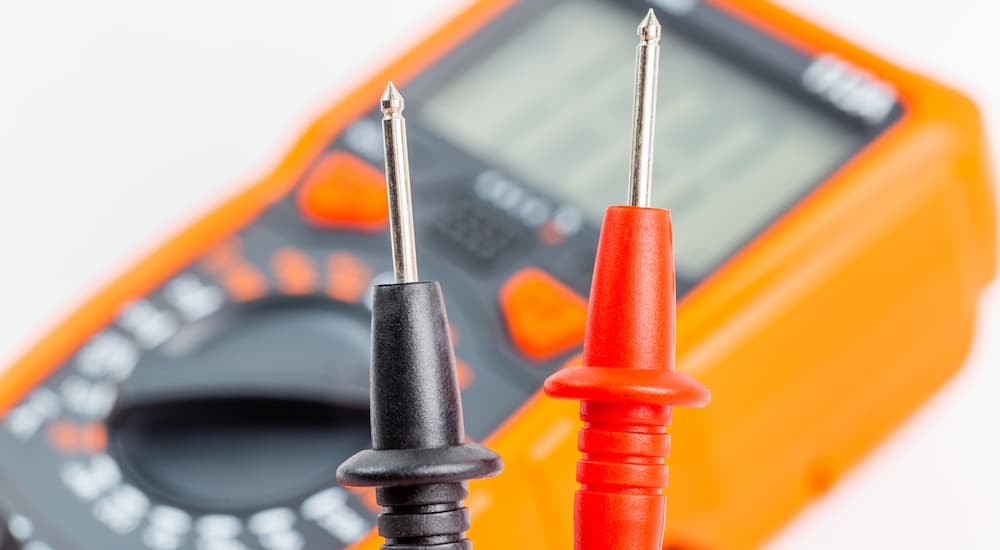
- Basic handheld digital multimeter with probes (bonus if the probes have clips)
- Fine grit sandpaper (100-200 grit is about right)
- Electrical insulating gloves
Many people are probably comfortable doing this without gloves, as one might be comfortable rollerblading without knee pads. That’s okay! Electricity makes the hair on my neck stand up, and I’d like to be as safe as possible, so I’ll take my rubber gloves regardless of the system’s maximum voltage, thank you very much.
Why? Because accidental contact with an electrical conductor–an exposed wire, or even the metal tip of your multimeter probe–can result in an uncomfortable jolt at best and serious injuries at worst. ICE vehicles, which have 12 V batteries, are closer to “gotcha!” than they are to “get an ambulance!” on the pain scale, but you know what won’t hurt? Gloves.
Sandpaper will come in handy if any connections or terminals you want to check are covered by corrosion or other filth. You need a clean metal surface for your probe to contact.
Most important is the multimeter, the device that will measure the electrical performance of your circuits. $25 to $50 is about the right price for a decent handheld unit with appropriate versatility for household use and the capacity to safely handle over 240 V. These fantastic little devices are super easy to use and come in handy whenever anything that runs on lightning isn’t working as it should.
Just give it a once-over to ensure there are no obvious signs of damage to the multimeter, probes/clips, or any part of the wires. A damaged multimeter is no longer a safe multimeter, and the same goes for the probes, even if the damage is as simple as a crack in the rubber insulation. Sweat from your hand pressing into that crack will be more than enough to make your hand a part of the electrical circuit–and by extension, the rest of you (unless your hand is not attached to your body, in which case you are reading the wrong guide).
Step #2: Prep your work area.
Maybe this should come first because if your car is outside and it’s raining or foggy, I recommend hitting the “NOPE” button and trying again another day. Water–or more importantly, the minerals, ions, and other stuff that loves to dissolve in water–is an excellent conductor of electricity. Never, I repeat NEVER, mix the two.
See an electrical cord laying in water? Don’t touch or step in that.
Are your hands all wet? Dry ’em. Is your car parked in a puddle? Move it, or wait until the puddle is gone.
There isn’t much left to do other than find a work buddy. It never hurts–and on more powerful systems, it can be critical for preventing loss of life–to have a buddy around to keep an eye on you. When it comes to vehicle diagnostics, you’ll sometimes need that buddy in the driver’s seat to operate the electrical systems while you run the multimeter.
Step #3 Take your measurement.
Taking the measurement of interest can be extremely simple. For starters, prep your multimeter accordingly. One of your probe wires should be black to represent the electrical ground. Naturally, as an engineer with two degrees and an active phobia of electricity, I need to check the definition of “ground” twice a year. “Ground” represents a drain or an outlet for electricity to harmlessly escape from the system to the Earth and is an essential component of any electrical system. By plugging in this black wire probe to the ground port on the multimeter (typically labeled “COM”), you’ve essentially connected a drain for electricity that might need to escape the system.
There may be two or three other ports for the red probe to plug into on the multimeter. The port depends on the measurement you want to take. Usually, there will be two–one with an “A” or “10A” beside it, representing Amps or 10 Amps, and another with a bunch of symbols like “V” and “Ω” (read as “omega”), representing Volts and Ohms, the unit of electrical resistance. We’re measuring voltage and resistance here, so that’s the port we’re interested in using.
Next up: set the multimeter to the measurement you want to take. Let’s start with voltage. You may see two points on the dial, or two areas, marked with V. One will have a squiggle “~” above the V, the other a flat bar over three dashed lines. These represent alternating current and direct current (AC and DC), respectively; we want the DC kind for an automobile. If there’s a range of numbers to choose from, “20” or thereabouts will do; the numbers represent the maximum value the multimeter can display under that setting. For the most accurate results, choose the smallest one that’s still higher than what you’ll be measuring, which in this case is a 12 V vehicle system, hence a 20 V maximum.
Now we’re ready to test whatever it is we’re going to test!
Potential Problems: Testing Voltage
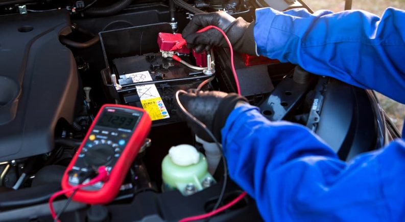
The most likely scenario is that you’re trying to gauge the health of your battery. There are a few actions to take here. First, ensure the contacts are clean (use the sandpaper if needed), then touch the black probe to the negative (-) contact and the red probe to the positive (+) contact. Your multimeter will display the “potential” or voltage of the battery, which is like an electric equivalent to water pressure. A charged 12 V battery will read out something around 12.5 V. I know it’s counter-intuitive, but it makes sense to electricians, so don’t sweat it. According to JD Power, a reading under 12.2 V indicates that the battery needs a charge or replacement because it isn’t holding enough charge for normal operations.
If you ask your buddy to hop behind the wheel and start the engine, the battery will send a lot of energy to the starter, and you’ll observe a voltage drop on the multimeter. The critical number to watch for is 10 V; a healthy battery will stay above that threshold even while cranking the engine. Lastly, you’ll see the voltage increase as the alternator gets to work. Give the reading some time to stabilize and look for a steady number over 14 V, a healthy threshold for reliable operation.
You can easily take this one step further and test the alternator by asking your buddy to let loose on the vehicle’s electrical system. Headlights, radio, heated seats, you name it, tell them to turn everything on and max out the load on that battery! Watch the reading on your multimeter drop as the “pressure” of the electrical system drops from just over 14 V to 13.5 V or so. Anything under 13 V indicates that the alternator isn’t keeping up, so ask your mechanic for a second opinion before it has a chance to fail while you’re out on the road (trust me, that is not a fun idea for a January date night).
Welcome to the Resistance!
Electrical resistance is the friction of the electrical world. For a given potential in V, the amount of current (A or amps) that flows through the circuit depends on resistance (Ω, omega, or Ohms). Think of applying water pressure to a plumbing system–the more resistance there is to water flow, say from filters in the pipeline, the slower the flow will be, and vice versa. Every conductor offers some resistance, but the resistance is very low for good conductors like copper. On the other hand, insulators like rubber have extremely high resistance. The filaments in an incandescent bulb fall somewhere in the middle; passing electricity through them isn’t easy, and the electrical energy lost by flowing through them turns into enough heat that the filaments glow, providing light!
A resistance check is helpful to determine if a fuse is blown or if something in an electrical circuit has broken. In this setting, the multimeter will send a very small current through the probe wires and calculate resistance based on the voltage it needs to apply to generate that current. Using the water flow analogy again, this is like increasing the pressure output from a pump until the flow rate reaches a predetermined value. If more pressure or potential is needed, there’s more resistance in the system.
Step 1 is to turn off whatever you’re going to be working on. Because the measurement depends on sending a small current through a system, you don’t want any other sources interfering with their input. To check resistance, you can turn your multimeter’s dial to Ω or to someplace in the Ω zone. If you have multiple options, it indicates the scale or decimal location. As before, use the setting as close as possible to what you expect to see without going under like a backward Price Is Right game.
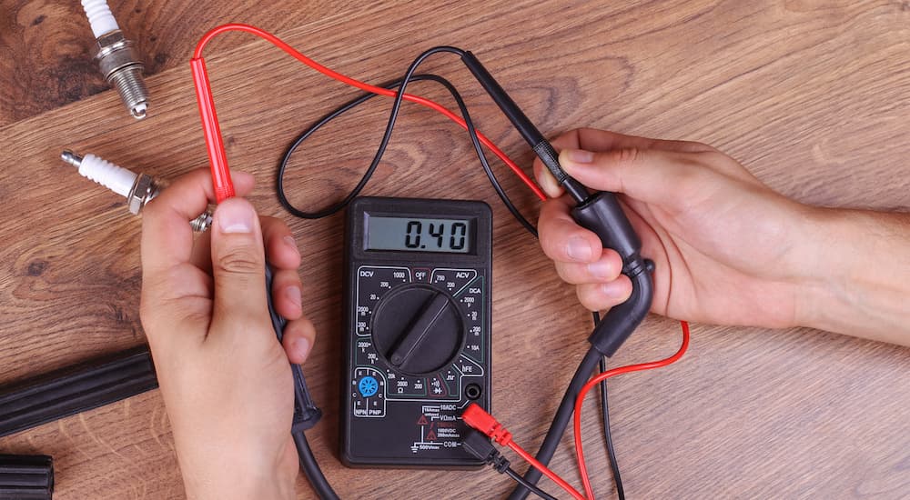
To check a fuse, use the smallest setting for Ω that you have since a fuse is supposed to have extremely low resistance. Watch the readout on your multimeter as you apply your probes to the fuse caps; a low reading indicates that everything is working fine! But if the value doesn’t change, the resistance between the two probes is the same as when they’re not touching anything at all, meaning the fuse has blown and needs to be replaced.
Other electrical devices like a headlight can be checked via resistance testing too. As Emanual Online describes, first identify the ground wire by seeing which one is connected to the car’s chassis. Apply one probe to the end of that wire and another to the battery’s negative terminal. If there’s no reaction from the multimeter, something has broken to disconnect those points!
Everybody’s Pullin’ Benjamins
Hopefully, this helps you take a safe, cautious step into the world of electrical vehicle diagnostics. If you can perform some of these routine checks without feeling like a modern Ben Franklin flying a kite in a thunderstorm, I call that a win! Electricity may be as terrifying and mysterious as a celestial being, but in reality, it’s a predictable force of nature that we can all safely interact with. There’s no need to shield your eyes, fall to your knees or wear a particular uniform; just the gloves will do.